- Commissioning
- Connect devices
- Ripple controller
Ripple controller
This page describes the connection of a ripple controller to the EnergyManager pro. Signals for reducing the feed-in power are received via a ripple controller.
Compatibility
| Energy Manager pro | Manager flex | |
|---|---|---|
| Ripple controller |
A ripple controller can be connected directly to the S0 interfaces or to a Digital extension can be used.
Connection to the S0 interfaces
EnergyManager pro only!
Interfaces: S0 1, S0 2
A ripple controller is connected directly to the EnergyManager via the two S0 inputs.
- Protect the work area against accidental contact with live parts.
- Connect the signal outputs of the ripple controller to the S0 inputs of the EnergyManager. If the ripple controller has a single negative pole for each output, connect all negative poles to the respective negative S0 input.
- The terminals of the ripple controller are assigned to the S0 inputs of the EnergyManager in accordance with the terminal assignment specified by the energy supply company.
Assignment example
The following table shows an example of a possible assignment of the ripple control channels and the S0 inputs to be used on the EnergyManager. Always observe the terminal assignment regulations of your energy supply company.
| Ripple controller - channel / Power level | Power level | S0 interface on the EnergyManager pro |
|---|---|---|
| 1 | 100% | without |
| 2 | 60% | S0-1 |
| 3 | 30% | S0-2 |
| 4 | 0% | S0-2 |
The 100% power level means: no curtailment; the 0% power level means curtailment to 0% output power, i.e. full curtailment.
Allocation plan
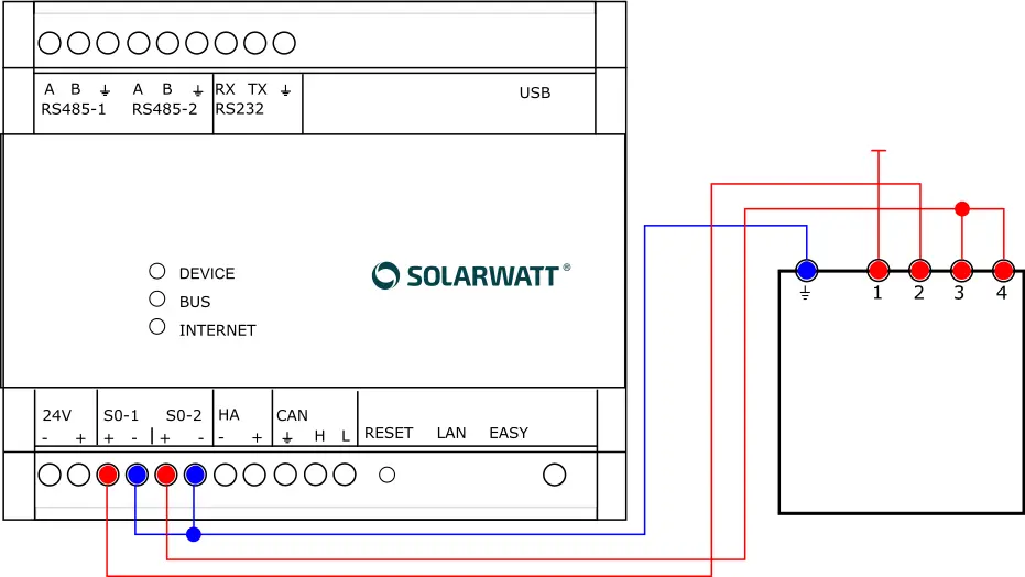
Connection diagram for ripple controllers to the S0 interfaces of the EnergyManager pro.
It should be noted that, for circuit-related reasons, curtailment to power level 0 (in the example: 0%) occurs when the grid operator specifies curtailment to power level 3 (in the example: 30%). The reason for this is the parallel connection of terminals 3 and 4 at S0 input 2.
Setup in SmartSetup
Search for devices
- Select the ripple controller in the drop-down menu under Other devices.
- In the configuration menu, select 2 under Number of interfaces
- Assign the corresponding input on the EnergyManager to each interface. Observe the specifications in the operating instructions of the ripple controller or the grid operator.
- The power levels are configured on the right-hand side of the configuration menu. The number of possible power levels is determined by the number of interfaces used. A tick means that a signal is present at the interface.
- Define the power levels according to the grid operator's specifications. Power level 100% = no curtailment, power level 0% = curtailment to 0% output power, i.e. full curtailment.
The power levels refer to the cumulative system power of all PV plants. This is defined in the "PV plants" setup step in Smart Setup.
The following illustration shows the settings to be made for the assignment example shown above.
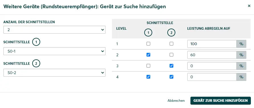
Due to the number of available S0 inputs, not all 4 power levels of the network operator can be implemented. However, it is ensured that there is always sufficient curtailment when a control signal is received.
PV plants
- Under Curtailment of all PV plants, select Curtailment via ripple controller.
Consumption-dependent curtailment: No more than the power defined in the active power level is fed into the utility grid. The curtailment takes into account the household consumption. The power generated by the inverters is therefore usually higher than the power level values.
Rigid limitation of the inverter: The total generation is limited to the respective power level. Domestic consumption is not taken into account.
Connection to the Digital Extension
EnergyManager pro only!
Interfaces: DI 1, DI 2, DI 3, DI 4
Alternatively, a ripple controller can also be connected via the Digital In inputs on a Digital Extension.
- Protect the work area against accidental contact with live parts.
- Connect the signal outputs of the ripple controller to the Digital In interfaces of the Digital Extension. If the ripple controller has a single negative pole for each output, connect all negative poles to the ground contact of the extension.
- Note the following assignment of the interfaces between the EnergyManager - Digital Extension and the ripple controller:
Digital Extension interface | Ripple controller interface |
|---|---|
1 | 3 |
2 | 4 |
3 | 1 |
4 | 2 |
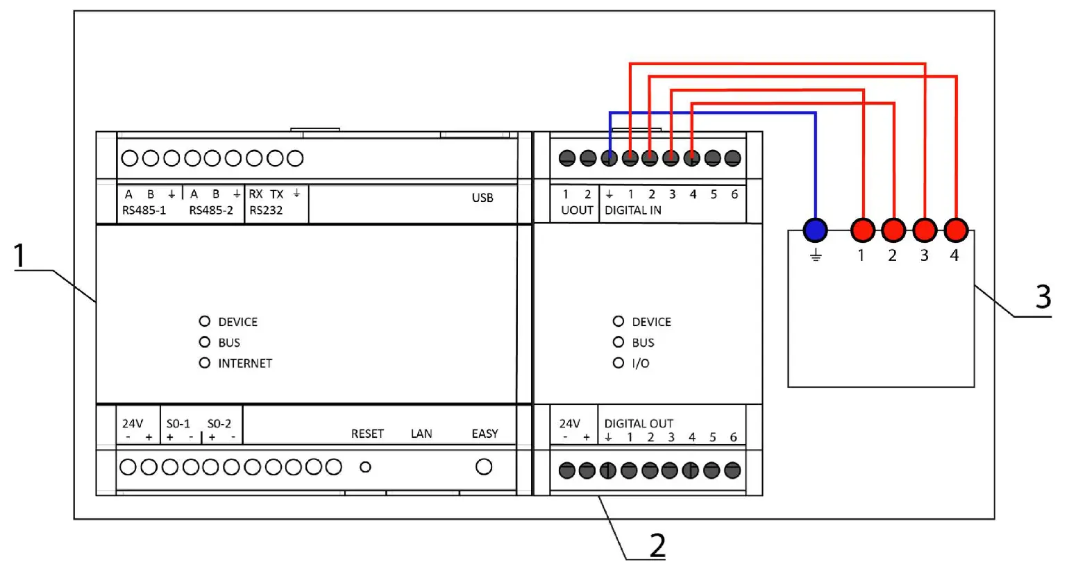
Connection diagram for ripple controller to the inputs of the Digital Extension.
Connecting a ripple controller to the Digital Extension
1 | Energy Manager |
2 | Digital Extension |
3 | Ripple controller |
Setup in SmartSetup
Search for devices
- Select the ripple controller in the drop-down menu under Other devices.
- In the configuration menu, select the number of interfaces to which the ripple controller is connected.
- Assign the corresponding input on the EnergyManager to each interface. Observe the specifications in the operating instructions of the ripple controller or the grid operator.
- The power levels are configured on the right-hand side of the configuration menu. The number of possible power levels is determined by the number of interfaces used. A tick means that a signal is present at the interface.
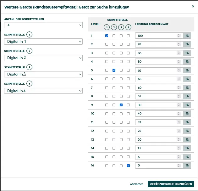
Example: Configuration of a ripple controller connected via 4 interfaces
In the example, the ripple controller is connected to the EnergyManager via the Digital In 1, Digital In 2, Digital In 3 and Digital In 4 interfaces of the Digital Extension.
Information is transmitted from the grid operator by activating individual interfaces alone. The following performance levels should be defined:
| Controlled interface | Power level in % |
| 1 | 100 |
| 2 | 60 |
| 3 | 30 |
| 4 | 0 |
Several interfaces are not controlled simultaneously by the network operator. Nevertheless, the power level must be defined pro forma for all possible combinations. All combination options are preselected by default. In order to implement the configuration specified in the table above, the power values of levels 1, 5, 9 and 16 have been adjusted. The values of the other levels were left unchanged from the default settings.
Define the power levels according to the grid operator's specifications. Power level 100% = no curtailment, power level 0% = curtailment to 0% output power, i.e. full curtailment.
The power levels refer to the cumulative system power of all PV plants. This is defined in the "PV plants" setup step in Smart Setup.
PV plants
- Under Curtailment of all PV plants, select Curtailment via ripple controller.
Consumption-dependent curtailment: No more than the power defined in the active power level is fed into the utility grid. The curtailment takes into account the household consumption. The power generated by the inverters is therefore usually higher than the power level values.
Rigid limitation of the inverter: The total generation is limited to the respective power level. Domestic consumption is not taken into account.
Selected articles: