- SOLARWATT Battery & Inverter vision
- Installation
- Installing Inverter vision one
Installing Inverter vision one
This page outlines the mounting and cable connection process for installing the single-phase SOLARWATT Inverter vision one inverter.
Table of contents
- Mount the inverter
- Connect the PV DC cable
- Connect the DC battery cable to the inverter
- Screw in the antenna (for Bluetooth support)
- Connect the BMS cable to the inverter
- Connect the inverter to the internet
- Connect the communication cable to the meter
- Connecting the AC-BACKUP
- Connect AC-GRID
- Connect the grounding cable
Mount the inverter
Observe all Safety Instructions and requirements for the installer.
Observe the Specifications for the installation location and the maximum and minimum installation distances between the inverter, meter and battery.
Check whether the condition of the wall and the enclosed mounting material are suitable for supporting the product weight of the inverter (22 kg).
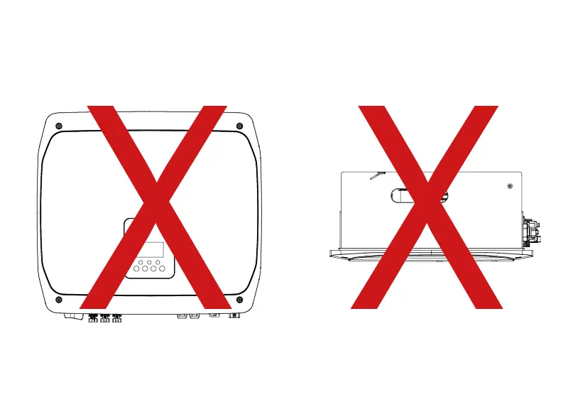
Do not rest the inverter on its connection ports or front panel.
- Mark, then drill the screw holes for the wall bracket
- Mount the wall bracket
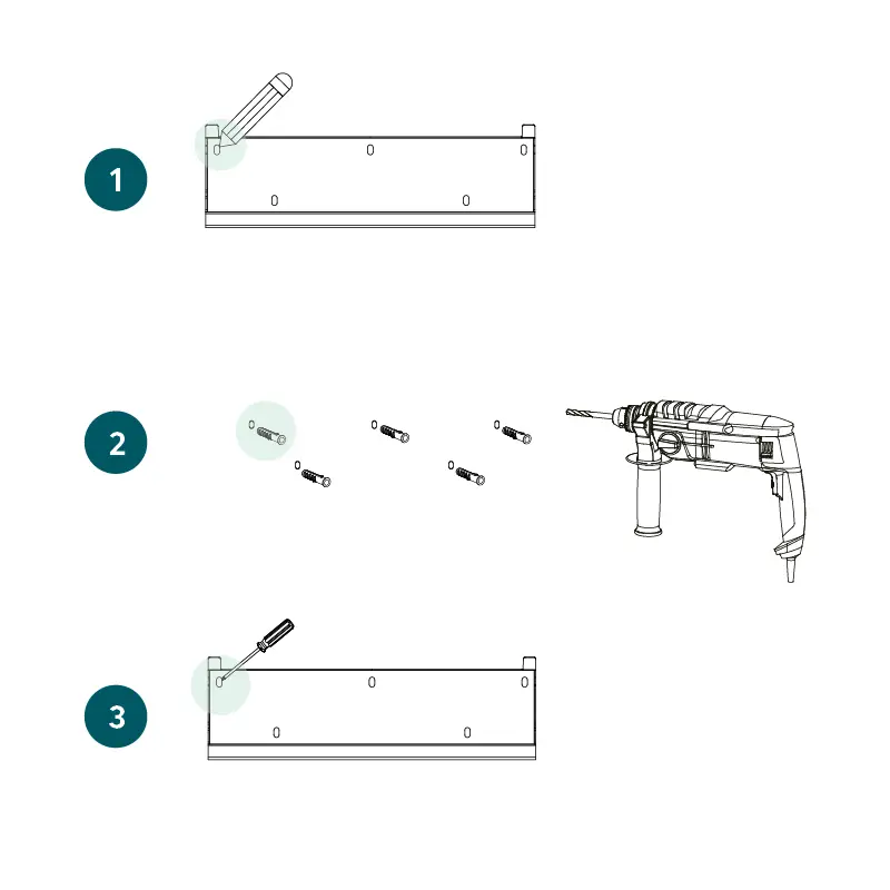
Mounting the wall bracket
- Carefully hang the inverter on the wall bracket along the groove guide
- Screw the inverter into both sides of the wall bracket
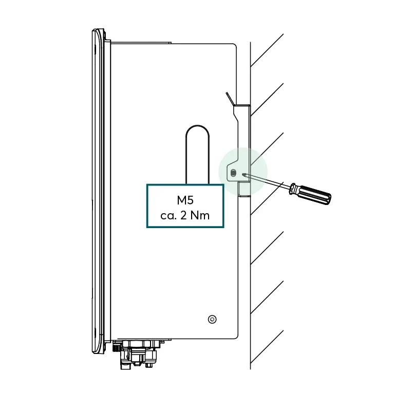
Screwing in the inverter
Video: Inverter vision one wiring
Connect the PV DC cable
Observe the Information on cable requirements and minimum bending radii for inverter, meter and battery.
Observe the Explanations on the Crimping PV plug connectors.
Inverter vision one includes Stäubli MC4 Evo 2A PV connectors in the box, which are compatible with the Stäubli PV connection sockets on the inverter. Stäubli PV plugs are compatible with other types of Stäubli MC4 plugs.
- Strip the PV DC cable to a length of 6.0 - 7.5 mm
Make sure that no individual wires are damaged! - Crimp the DC cable with the PV plug connectors
Ensure correct polarity when assigning the PV pin contacts!

Stripping the PV cable
- Connect the DC PV cable to PV+ and PV- on the inverter.
Listen for an audible 'click' to ensure the connector makes contact. - Pull on the DC PV plug connectors to ensure they are fully engaged.
(control force: max. 20 N)
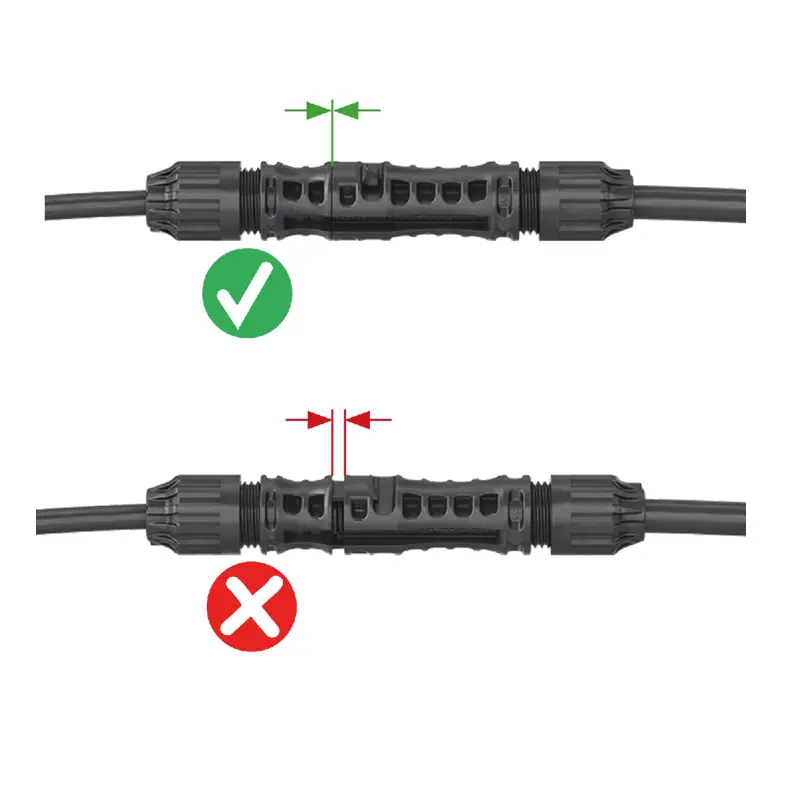
Plug connectors together right / wrong

Screw on the antenna
Connect the inverter to the internet
Inverter vision one must be connected directly to the router via a LAN cable connection. A LAN cable for this purpose is not included in the scope of delivery.
Observe the requirements for the cable type for the communication connection under Required accessories and tools.
- To protect the connection in wet room and outdoor installations, the connector housings included in the scope of delivery of the inverter must be used on the inverter side
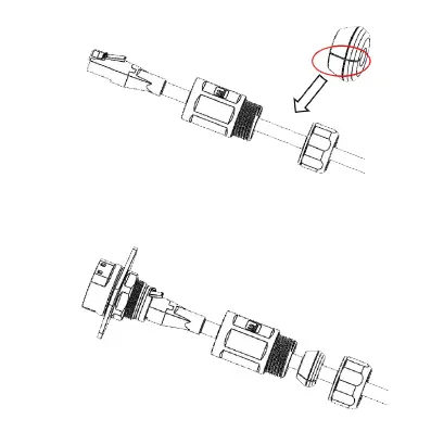
Slide the seal over the cable and secure all components of the connector housing
Note: When using an installation cable, it may not be possible to fit self-assembled plugs through the plug housing. In this case, make sure that the plugs used are UV and weather-resistant for outdoor use and that the required IP rating IP65 is maintained.
- Connect the other side of the cable to your router
In exceptional cases, the inverter can be connected to a Wi-Fi network in range of the inverter to allow it to connect to the internet.
- Ensure that the antenna is screwed in to the inverter
- Use the SOLARWATT Pro app to configure the Wi-Fi settings on the inverter
Further explanations on Connecting the inverter to the local network via Wi-Fi.
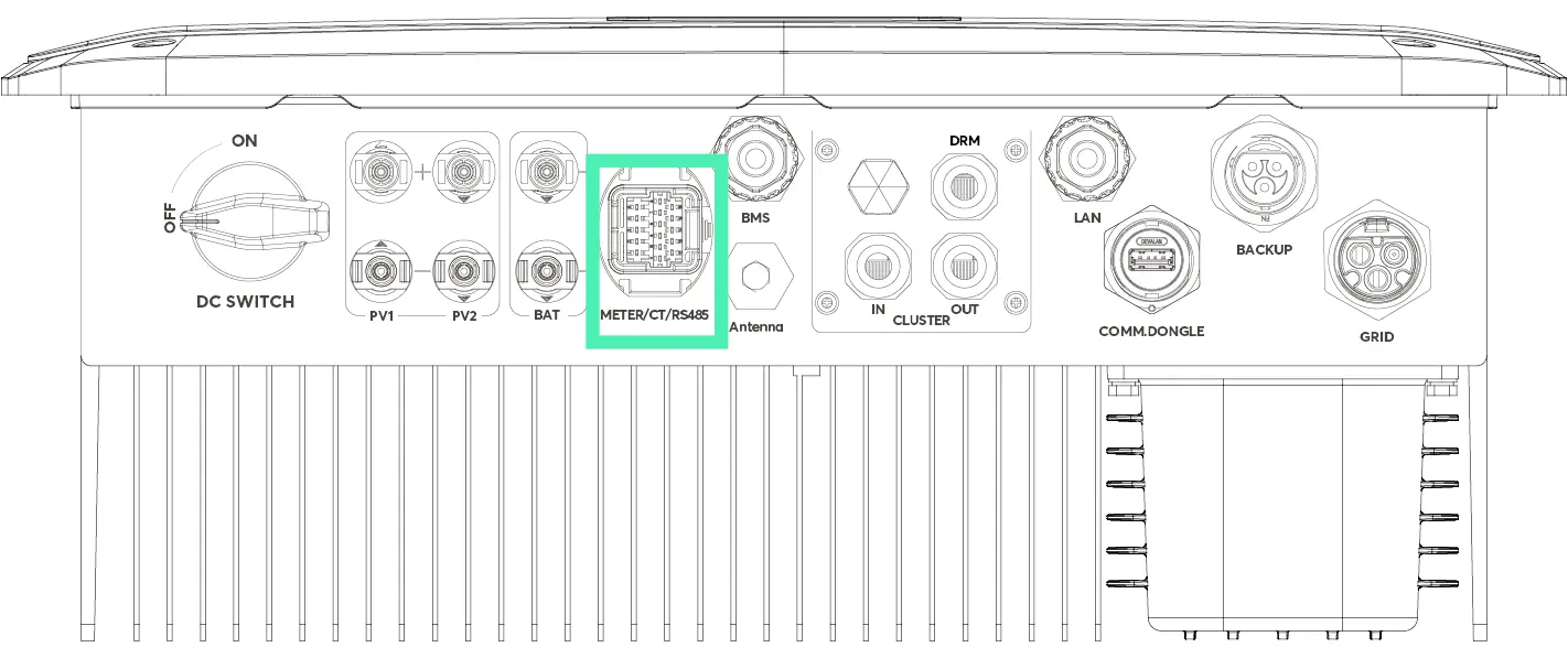
Connect the communication cable to the meter
Note: The following section explains how to establish communication with the single-phase meter DDSU.
Here you will find details on the communication connection of a 3-phase DTSU meter for 3-phase properties.
Observe the requirements for the cable type for the communication connection under Required accessories and tools.
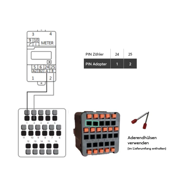
- Configure the adapter for connection to the meter (meter adapter is included in the scope of delivery of the Inverter one) and connect to the inverter
- Wire end ferrules are only necessary if stranded wires are used
The connection for communication with the DDSU meter is made via the direct connections 24 and 25.
Connecting the AC-BACKUP
Inverter vision one is designed for operation on the single-phase mains, voltage range 220/230/240 V, frequency 50/60Hz. Other technical requirements must comply with the requirements of the local grid.
Please note the Cable requirements and bending radii for inverter, meter and battery.
The AC-BACKUP plug (red ring) is included in the Inverter vision one box.
- Remove the transport protective covers from the AC-BACKUP port on the inverter
Loosening the protective covers of the AC-BACKUP connection for transportation
- Strip 40 mm of the AC cable
- Shorten the N conductor and L conductor by 9 mm so that the PE conductor can establish a connection all the way to the end of the cable
- Strip 9 mm of PE, N and L insulation
- Crimp on wire end ferrules
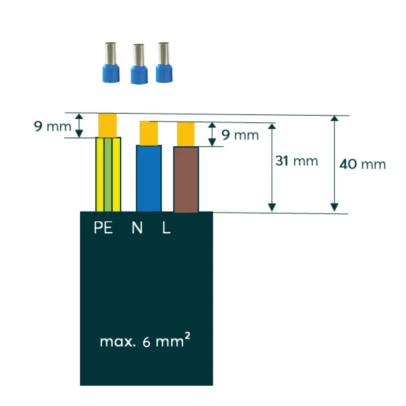
Strip, strip, use ferrules
- Feed the AC-BACKUP cable through the AC-BACKUP plug
- Connect the cable cores to PE, N and L as marked on the plug
- Screw the plug together
- Listen for an audible 'click' sound, which indicates the assembly has successfully locked in place
Configuring the AC-BACKUP plug
- Connect the AC cable to the AC-BACKUP port on the inverter
- Turn the plug ring to the right until it audibly locks into place
Connect AC-GRID
Inverter vision one is designed for operation in the single-phase mains, voltage range 220/230/240 V, frequency 50/60Hz. Other technical requirements must comply with the requirements of the local grid.
Please note the Cable requirements and bending radii for inverter, meter and battery.
The AC-GRID plug (white ring) is included in the Inverter vision one box.
- Remove the transport protective covers from the AC-GRID connection on the inverter
- Strip 55 mm of the AC cable
- Shorten the N conductor and L conductor by 9 mm so that the PE conductor can always establish a connector right to the end
- Strip 9 mm of PE, N and L insulation
- Crimp on wire end ferrules
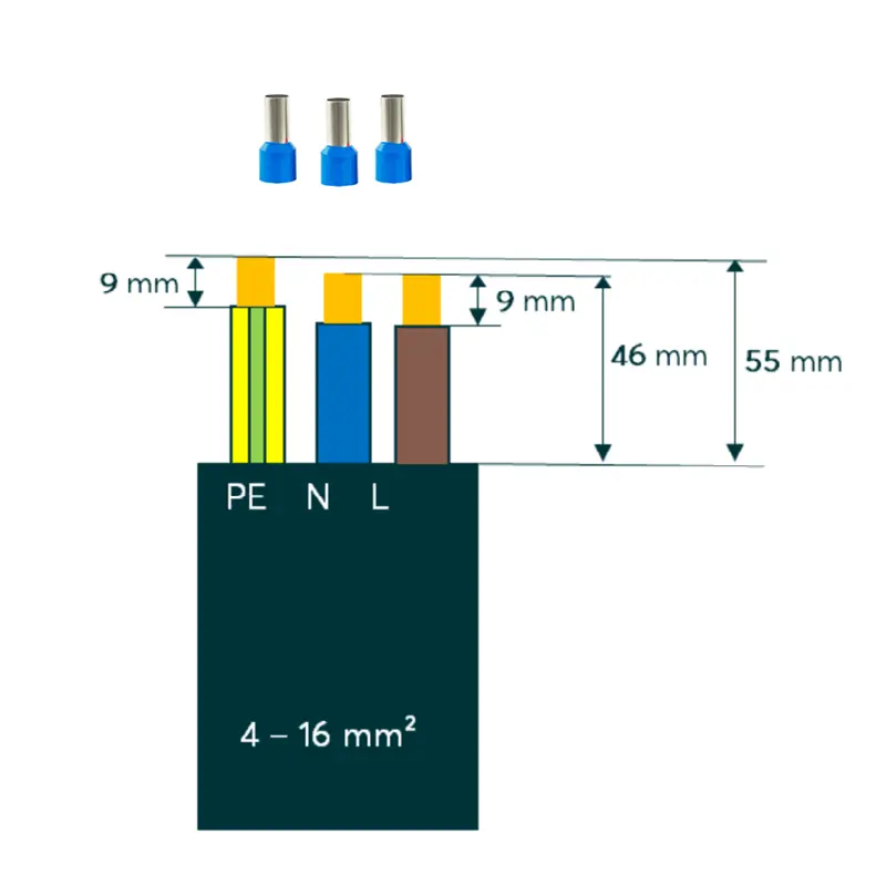
Strip, strip, use ferrules
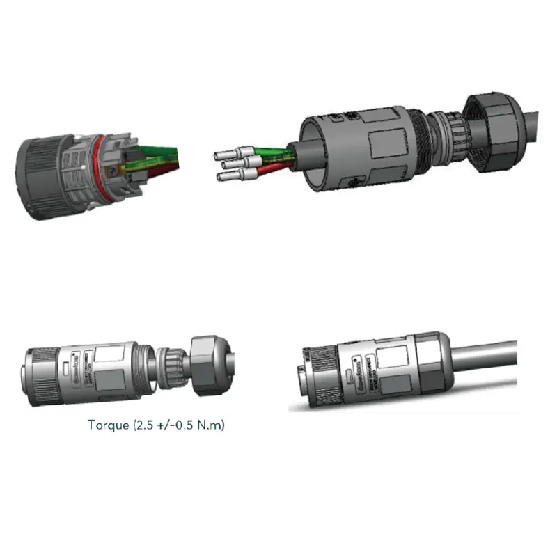
- Feed the AC cable through the AC-GRID plug
- Connect the cable cores to PE, N and L as marked on the plug (torque 3.0 ± 0.2 Nm)
- Tightly screw the assembly into place, listening out for an audible 'click' sound
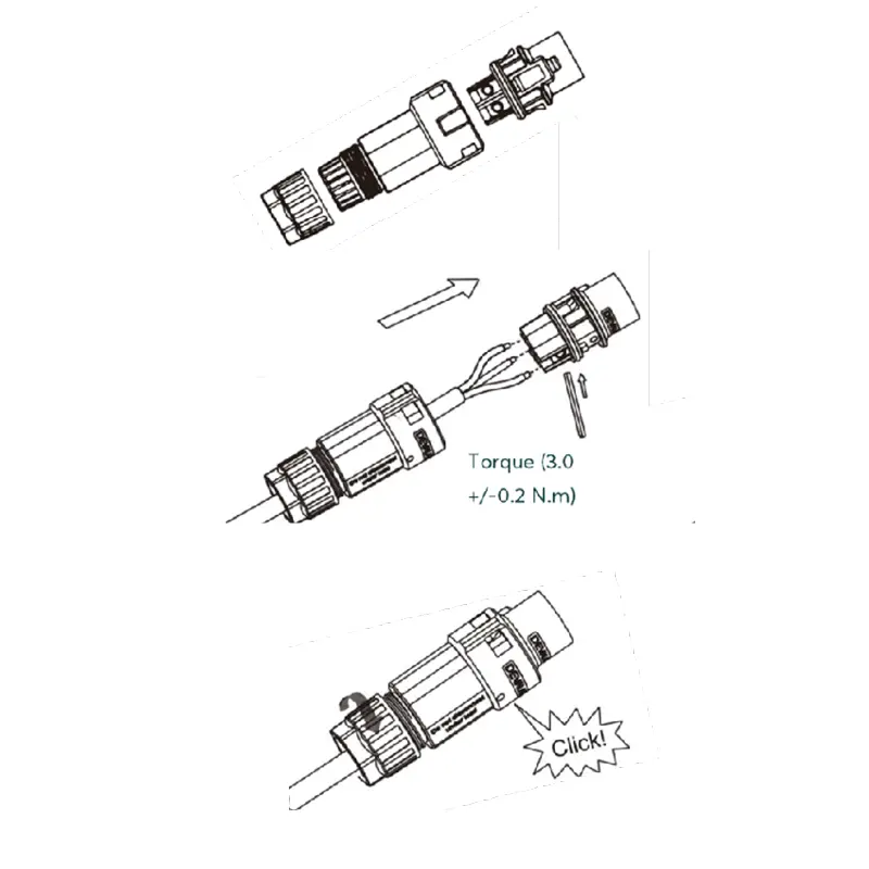
Assembling and closing AC-GRID plugs
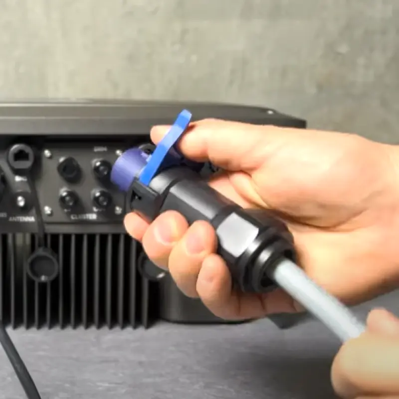
Fit the opening tool and push the plug out towards the front
- Connect the AC cable to the AC-GRID port on the inverter
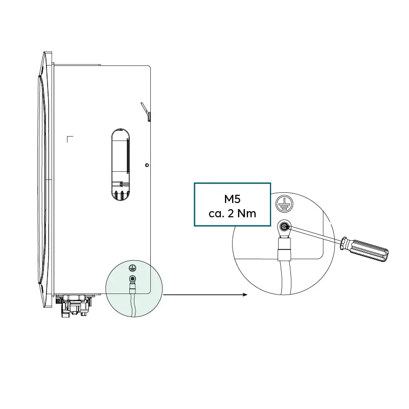
Connecting the grounding cable