- SOLARWATT Charger vision
- Installation
- Load management (optional)
Load management (optional)
This chapter describes how dynamic load management works and how to install it.
Functionality
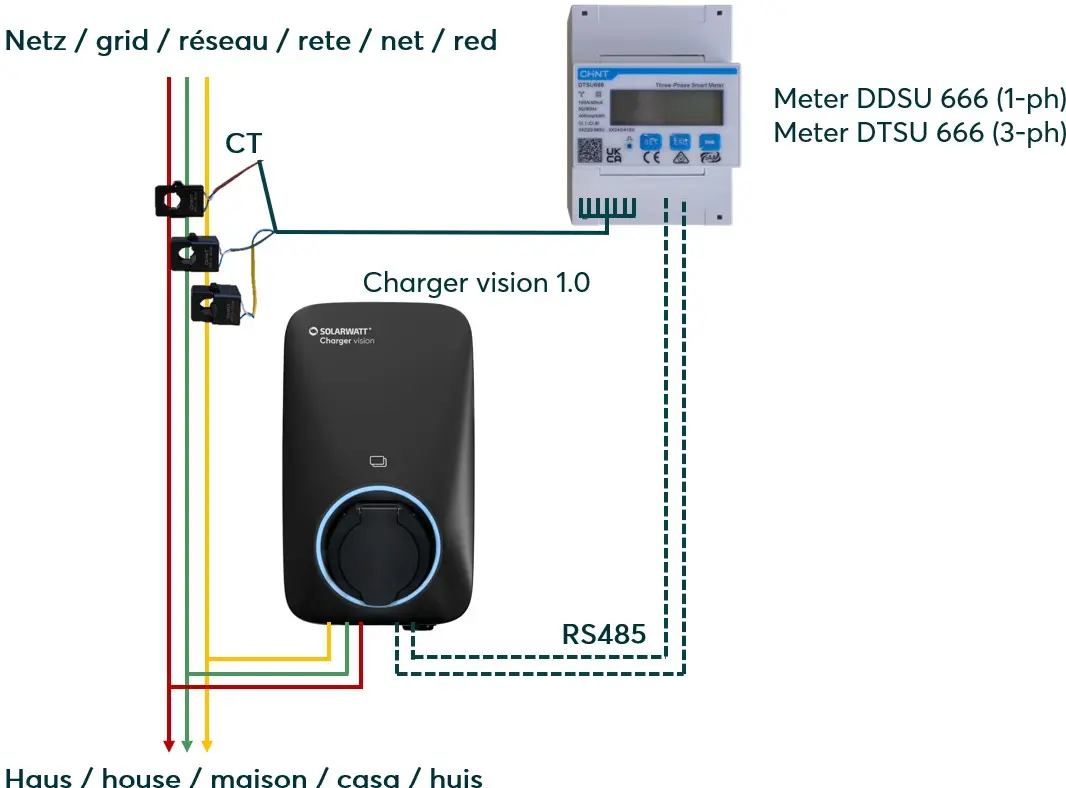
If the available grid connection power is not sufficient to cover the house load and the maximum power of the Charger, the charging power of the Charger can be regulated via dynamic load management so that a defined maximum current (maximum power) at the grid connection point is not exceeded (house load + charging power). For load management, a compatible electricity meter must be installed at the grid connection point and connected directly to the Charger via an RS485 communication line.
Notes / Restrictions
- Power control takes place within 1 - 3 seconds.
- Parallel power control of several Charger vision units is not possible; a maximum of one Charger vision unit can be connected to the electricity meter.
- The RS485 port on the electricity meter can be used for the inverter and the Charger.
- The RS485 port on the Charger can be used either for load management or for the external control box (§14a EnWG); parallel operation is not possible.
Compatible electricity meters
- SOLARWATT Meter DDSU 666 (single-phase)
- SOLARWATT Meter DTSU 666 (three-phase)
Technical data:
- 4 sub-units DTSU 666 (three-phase) / 2 sub-units DDSU 666 (single-phase)
- Measuring range up to 100 A per CT terminal
- CT terminals with 6 m cable length (extension up to 15 m)
- Max. Max. distance to the charger 100 m (RS485 cable)
Installation
This chapter only describes the installation of the electricity meter superficially. Detailed information can be found in the separate installation instructions for the electricity meter:
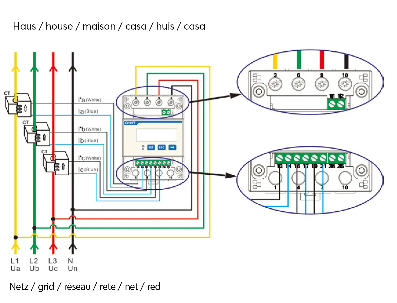
Installation instructions Electricity meter DTSU 666 (three-phase)
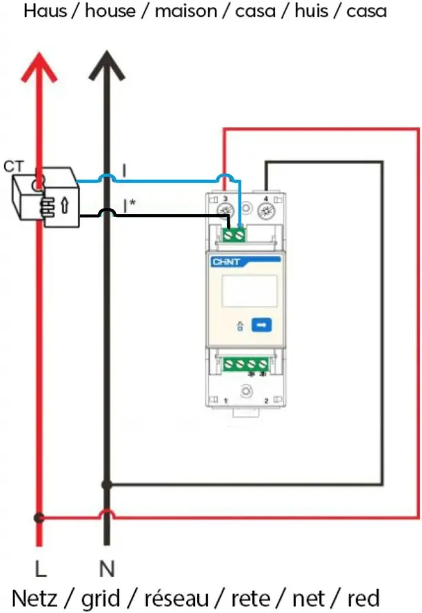
Installation instructions DDSU 666 electricity meter (single-phase)
- Install the electricity meter in the control cabinet (4HP).
- Install the enclosed CT terminals to measure the current in the domestic installation. The CT terminals must be positioned in the switch cabinet so that the total current can be measured before transfer to the domestic electricity meter.
- Pull a direct control line for communication between the electricity meter and Charger (RS485).
- Configure the charger via the SOLARWATT Pro app, activate load management and define the maximum current.
- The electricity meter records the total load at the grid connection point (house load + charging power) via transformer measurement and regulates the charging power of the Charger based on the current house load in order not to exceed a defined maximum current (power) at the grid connection point.
Installation of electricity meter DTSU (three-phase):
Installation of DDSU electricity meter (single-phase):
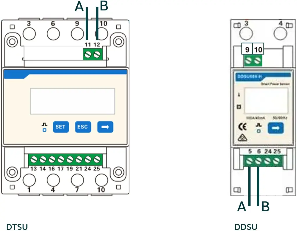
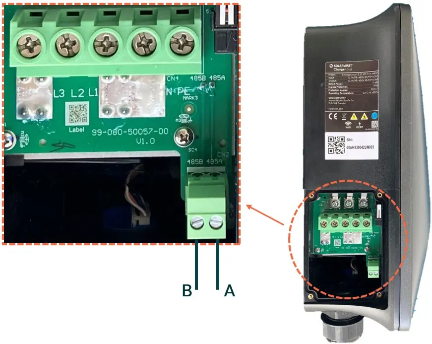
Installation RS485 communication:
Pin of the meter | Port / device | Conductor cross-section | Outer diameter |
DDSU (single-phase) | |||
5 | Pin 485A on the charger | 0.25 mm² - 1.5 mm² shielded, two-core twisted outdoor cable, min. Cat. 5e | 4 mm - 11 mm |
6 | PIN 485B on the charger | ||
DTSU (three-phase) | |||
11 | Pin 485A on the charger | 0.25 mm² - 1.5 mm² shielded, two-core twisted outdoor cable, min. Cat. 5e | 4 mm - 11 mm |
12 | PIN 485B on the charger | ||
RS485 pin assignment electricity meter:
RS485 pin assignment Charger:
Configuration
Load management is configured via the SOLARWATT Pro app.
- Activation of the load management
- Enter the maximum current at the grid connection point (house load + Charger charging power)
