- Home
- SOLARWATT Charger vision
- Installation
Installation
This chapter describes how to install the Charger vision.
Table of contents
Observe allSafety instructions and requirements for the installer.
Observe theSpecifications for the installation location and the maximum and minimum installation distancesfor the Charger.
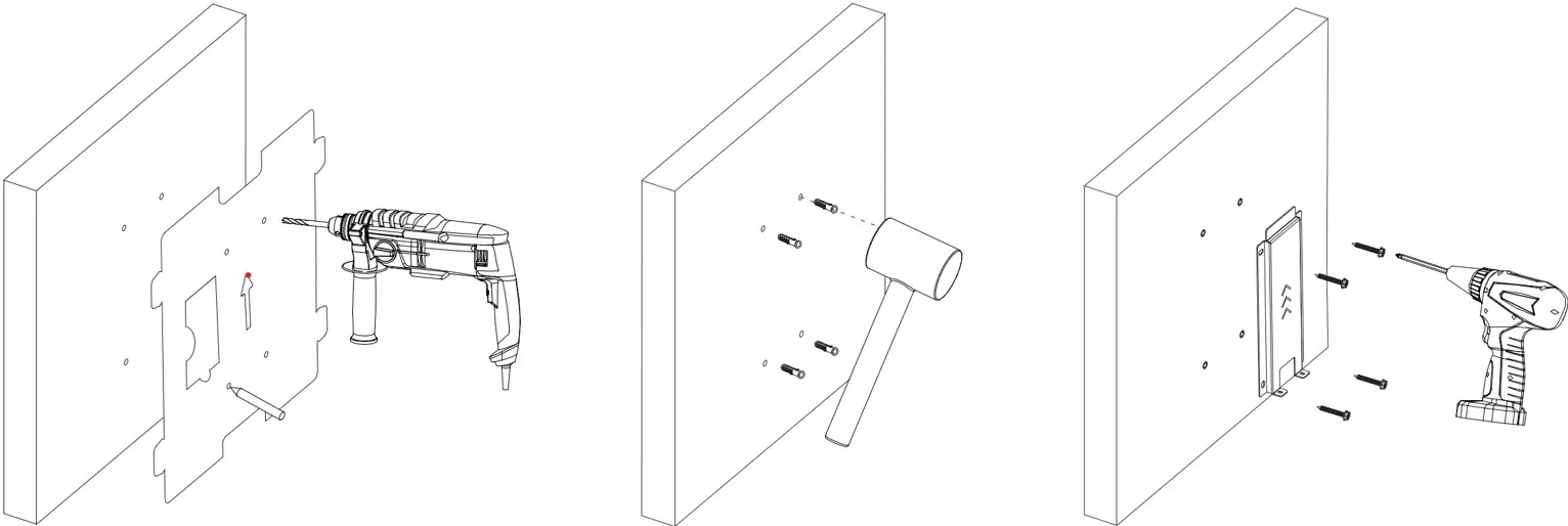
Wall mounting
Check whether the condition of the wall and the enclosed fastening material are suitable for supporting the product weight of the charger (5 kg) plus the tensile load (charging cable).
- Mark the drill holes using the drilling template and drill the drill holes
- Mount the mounting base plate using the fastening material
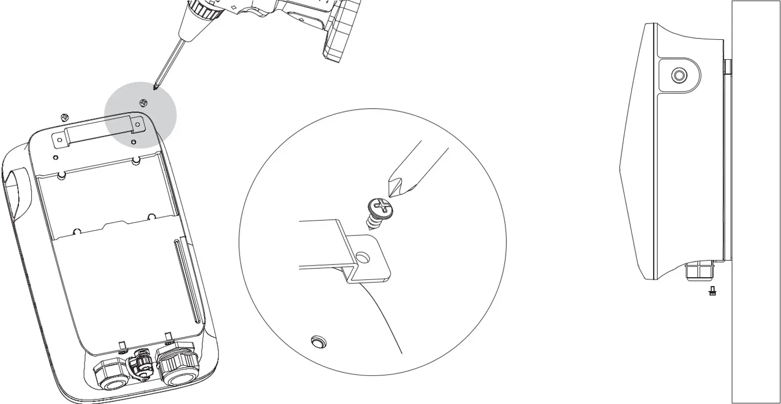
- Attach the mounting bracket to the charger using self-tapping screws
- Attach the charger to the mounting base plate and secure with the screws
Mounting upright (optional)
The Charger can optionally be mounted on a pedestal.
The pedestal is not included in the scope of delivery and must be ordered separately from Solarwatt.
The Charger vision is only compatible with the SOLARWATT Charger vision pedestal. Up to two SOLARWATT Charger vision can be installed on the SOLARWATT Charger vision pedestal.
A concrete foundation is required to install the pedestal, which must be provided by the customer.
Details on installation can be found here:
Network connection (LAN)
Self-assembled LAN cable:
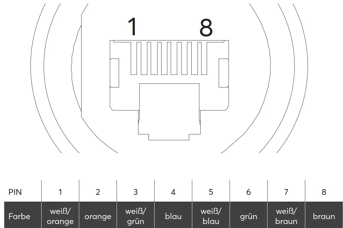
- Crimp the RJ45 plug onto the network cable
- PIN assignment of the network cable type B
Network connection to Charger:
- Feed the network cable through the union nut, insert the seal
- Insert the RJ45 plug into the RJ45 socket
- Tighten the lock nut and screw it to the charger
- connect the other end of the network cable to the router
Electrical connection
Three-phase:
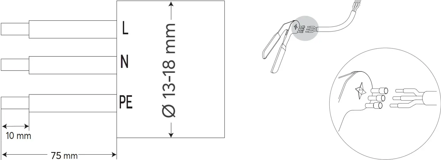
- Strip 75 mm of AC cable and strip 10 mm of insulation
- Crimp wire end ferrules onto the cables
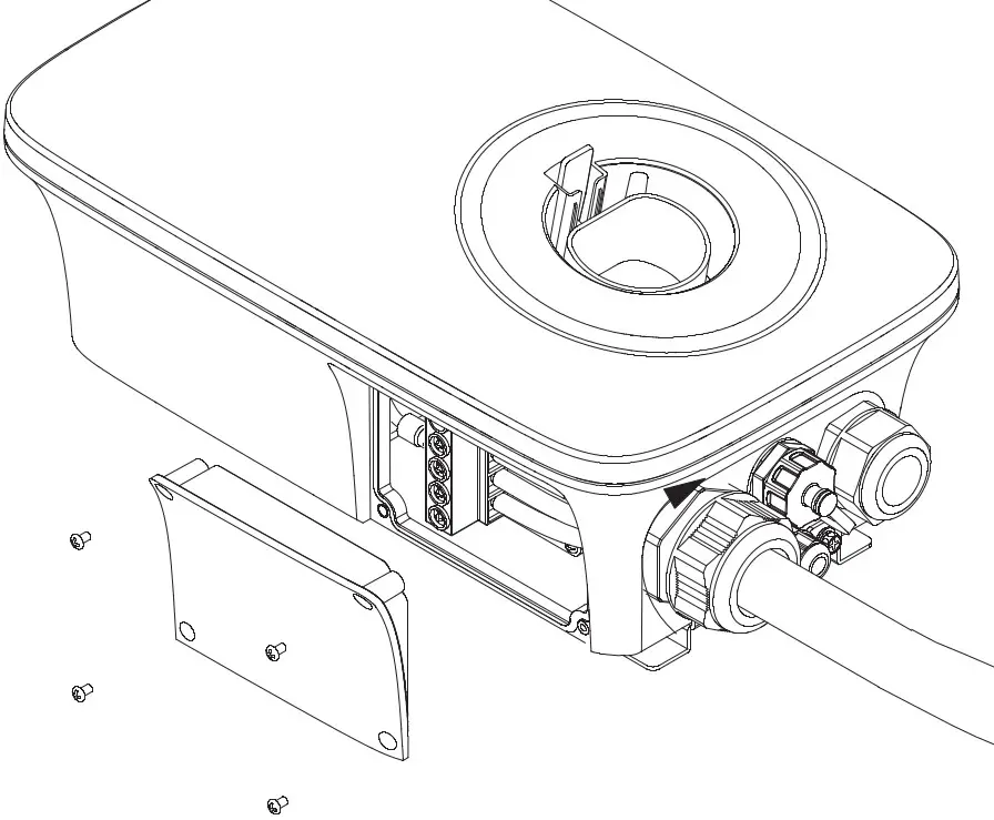
- Open the side cover to the AC connection area
- Loosen the cable gland and push the AC cable through it
- Install the AC cable
- Tighten the cable gland
- Close and tighten the side cover
- Tighten the cable gland (hold the 42 mm lock nut in place)
- Close and tighten the side cover
Single-phase:
- Strip 75 mm of AC cable and strip 10 mm of insulation
- Crimp wire end ferrules onto the cables
- Open the side cover to the AC connection area
- Loosen the cable gland and push the AC cable through it
- Install the AC cable
- Tighten the cable gland
- Close and tighten the side cover
- Tighten the cable gland (hold the 42 mm lock nut in place)
- Close and tighten the side cover
Load management (optional)
Dynamic control of the charging power taking into account the house load.
If the available grid connection power is not sufficient to cover the house load and the maximum power of the Charger, the charging power of the Charger can be regulated via dynamic load management so that a defined maximum current (maximum power) is not exceeded at the grid connection point (house load + charging power).
Details on how it works and how to install it can be found here:
External control box (optional)
§ Section 14a EnWG controllable consumption devices
Only required if the grid operator wants to reduce the charging power directly at the charger (e.g. ripple control receiver) or if no energy management is available.
Details on how it works and how to install it can be found here.
