- SOLARWATT Battery & Inverter vision
- Planning
- Hardware diagrams & scope of delivery
Hardware diagrams & scope of delivery
Table of contents
Hardware diagram:
Inverter vision three
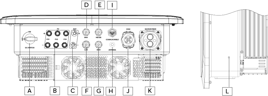
| A | DC switch | G | DRM connector |
| B | PV1, PV2, PV3 connection | H | Antenna (Bluetooth/Wi-Fi) |
| C | Battery connection | I | Comm. dongle USB port (unused) |
| D | Connection BMS (battery management system) | J | COM connection |
| E | Meter connection | K | Connection AC backup / AC grid |
| F | LAN connection | L | Earth connection |
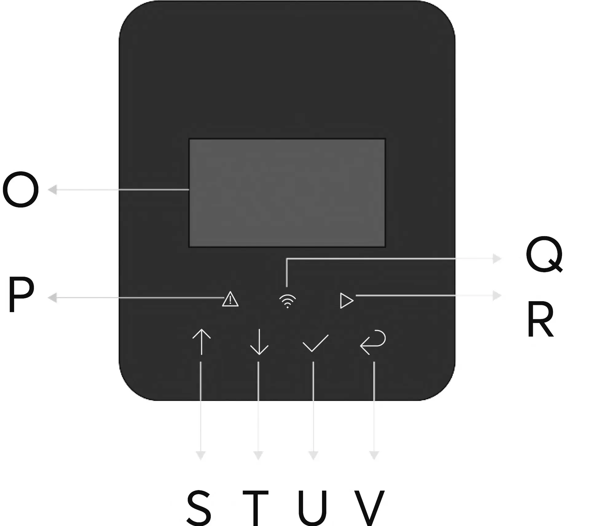
Inverter vision three display
| O | LC-Display | S | Up Button/Increase value |
| P | red: Error | T | Down Button/Decrease value |
| Q | blue: LAN/Wi-Fi status | U | Confirm Button |
| R | green: Ready for operation | V | Back Button/Exit menu |
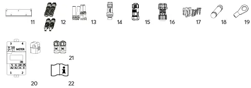
Scope of delivery:
Inverter vision three

In the Inverter vision three box
| 11 | Wall bracket | 17 | 3x Screws for inverter mounting |
| 12 | PV connector (Stäubli MC4) | 18 | Cable lug for earthing |
| 13 | PV pin contacts | 19 | 4x waterproof plug housings:
|
| 14 | AC plug | 20 | Antenna |
| 15 | Communication plug (optional) | 21 | Counter with CT terminals |
| 16 | 6x Screws and wall plugs for wall mounting | 22 | Quick start guide and safety instructions |
Hardware diagram:
Inverter vision one
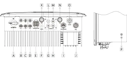
| A | DC switch | I | Comm. dongle USB port (unused) |
| B | PV1 | J | AC GRID connection |
| C | PV2 | K | BMS connection (battery management system) |
| D | Battery connection | L | Waterproof cover |
| E | Meter connection | M | DRM |
| F | Antenna (Bluetooth / WiFi | N | LAN connection |
| G | Cluster IN connection | O | AC BACKUP connection |
| H | Cluster OUT connection | P | Ground connection |
Scope of delivery:
Inverter vision one
In the Inverter vision one box
| 11 | Wall bracket | 17 | 4x screws for wall mounting |
| 12 | PV connector (Stäubli MC4) | 18 | Antenna |
| 13 | PV pin contacts | 19 | Cable lug for earthing cable |
| 14 | AC plug GRID (white ring) | 20 | Meter with CT terminal |
| 15 | AC.secker BACKUP (red ring) | 21 | 2x waterproof plug housings:
|
| 16 | Meter adapter with ferrules | 22 | Quick start guide and safety instructions |
Inverter vision one display
| O | LC-Display | S | Up Button/Increase value |
| P | red: Error | T | Down Button/Decrease value |
| Q | blue: LAN/Wi-Fi status | U | Confirm Button |
| R | green: Ready for operation | V | Back Button/Exit menu |
Hardware diagram:
Battery vision top pack & pack
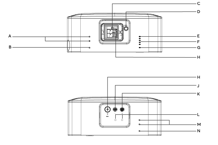

| A | Holes for mounting bracket | F | SoC LEDs | K | DC OUT+ | P | Hole for pack mounting |
| B | Hole for pack fastening | G | Status LED | L | Fasteners for DC cable | Q | Handle |
| C | B-Start switch | H | DC switch | M | Holes for mounting bracket | R | Status LED |
| D | Mains switch | I | BMS | N | Ground terminal | ||
| E | BMS status LED | J | DC OUT- | O | Pack fixings |
Scope of delivery:
Battery vision top pack & pack

In the Battery vision top pack box
| 1 | 4x screws (M5) for securing the wall brackets 2x screws for securing the top pack | 7 | 2x screws for wall fixing |
| 2 | Wall brackets | 8 | Jumper plug |
| 3 | Feet | 9 | Protective cover for pack connections |
| 4 | BMS inverter communication cable (1.5 m) | 10 | Safety instructions |
| 5 | Earthing cable with 2 additional cable lugs | ||
| 6 | DC cable (1.5 m) |

In the Battery vision pack box(es).
| 23 | 2x screws (M5) each for securing the pack |
| 24 | Safety instructions |