- SOLARWATT Battery & Inverter vision
- Installation
- Installing electricity meter DTSU 666 (three-phase)
Installing electricity meter DTSU 666
(three-phase)
This page outlines the installation and connection process for the three-phase meter DTSU 666.
Table of contents
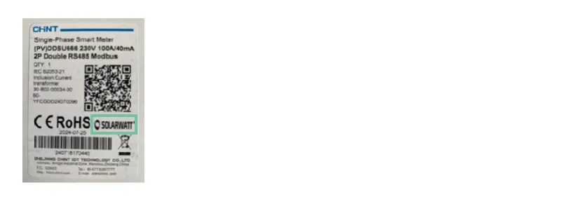
Label electricity meter Solarwatt version
Video: Electricity meter DTSU 666 overview
Technical specifications
Dimensions: 100 x 72 x 65.5 mm (4 HP)
Max. current: one CT terminal can be used for a measuring range of up to 100 A
CT terminal cable length: 6 m (can be cut to size or extended up to 15 m)
Max. distance to the inverter: 100 m
Installation of the meter with Inverter vision THREE in a THREE-phase system
Observe all Safety Instructions and requirements for the installer.
The Inverter vision three is supplied with the DTSU 666 duo RS485 CT three-phase electricity meter (Solarwatt version) for recording excess electricity and consumption.
When installing the meter, please refer to the wiring diagrams provided by Solarwatt for single- and three-phase systems.
- Hook the meter onto the top edge of the top-hat rail in the house connection box and press down until it clicks into place
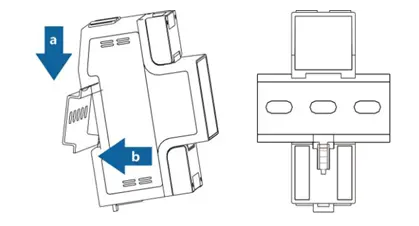
Mounting the meter on the top-hat rail
The voltage is measured via the direct connections of the DTSU 666:
- PIN 3 -> L1 Ua
- PIN 6 -> L2 Ub
- PIN 9 -> L3 Uc
- PIN10 -> N Un
The current is always measured via the enclosed CT terminals, which are connected to phase L1, L2 and L3 of the domestic installation.
The CT terminals must be positioned in the switch cabinet so that the total current can be measured before transfer to the domestic electricity meter.
A CT terminal can be used for a measuring range of up to 100 A.
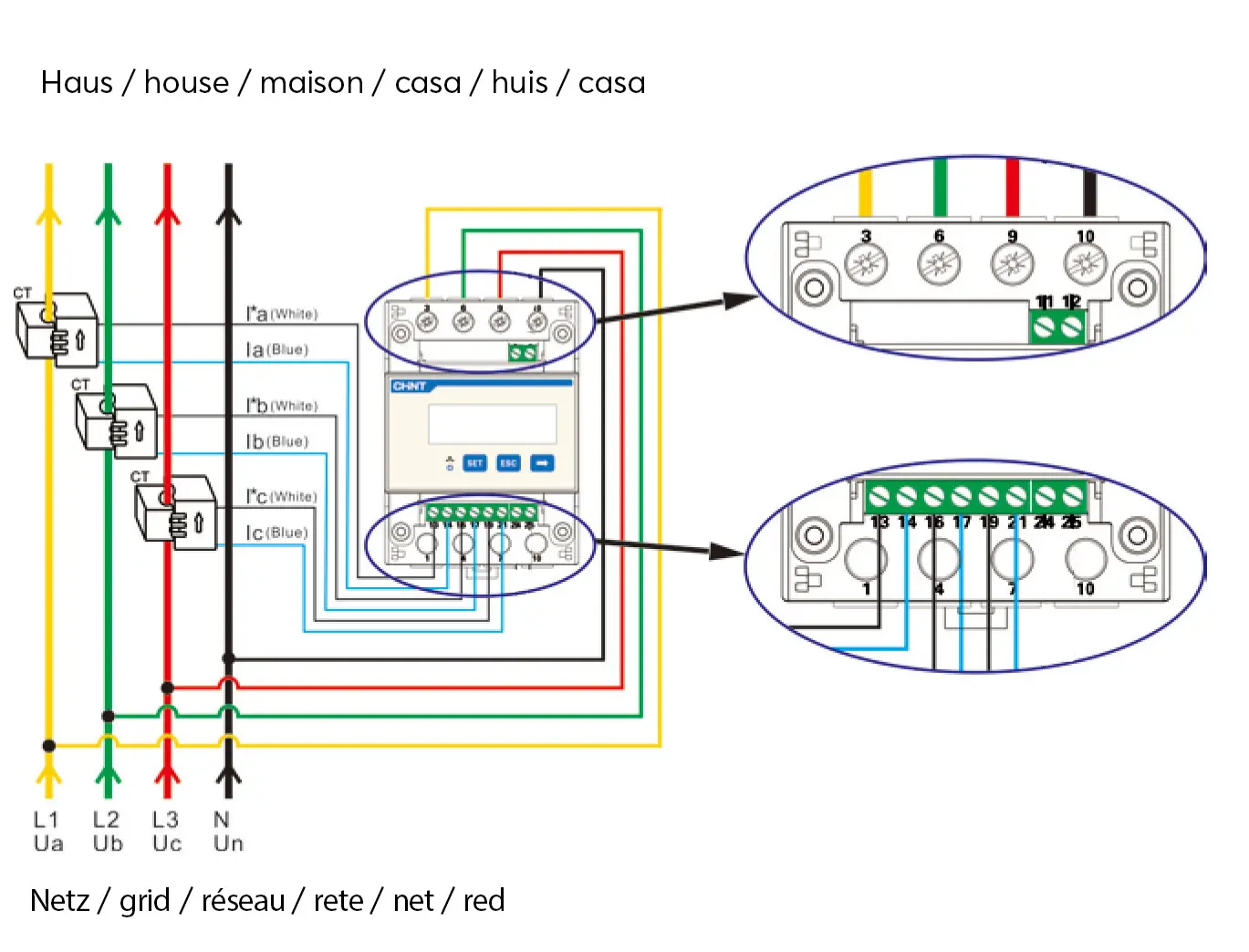
Current and voltage measurement DTSU
DTSU current and voltage measurement - pin assignment
| Pin of the meter | Port/device | Conductor cross section | Outer diameter | ||
| direct voltage measurement | 3 | L1 | 4 - 25 mm2 multi-core outdoor copper cable | 5 - 10 mm | |
6 | L2 | ||||
9 | L3 | ||||
10 | N | ||||
| Current measurement via CT terminal | 13 | Ia* (white) | yellow | - | - |
14 | Ia (blue) | ||||
16 | Ib* (white) | green | |||
17 | Ib (blue) | ||||
19 | Ic* (white) | red | |||
21 | Ic (blue) | ||||
- Connect the cable for voltage measurement
- Connect the cable for current measurement
- Only after doing the above, connect the CT terminals
The connection for communication with the Inverter three is made via the direct connections 24 and 25.
- Configure the RJ45 plug for the connector with the Inverter vision three inverter
- Attach the waterproof plug housing (included in the Inverter vision box) to the plug on the inverter side for protection and mechanical strain relief
- Connect the meter to the inverter using the RJ45 plug
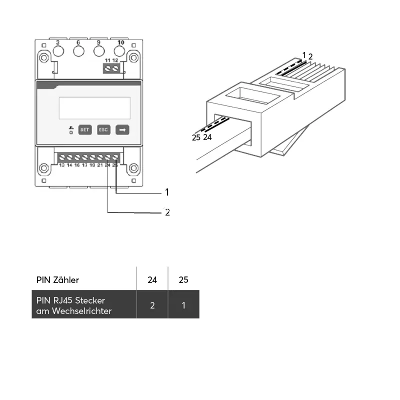
DTSU and Inverter vision ONE communication - pin assignment
| Pin of the meter | Port/device | Conductor cross section | Outer diameter | ||
| Outer diameter Communication | 24 | Pin 2 Counter adapter on inverter | 0.25 - 1.5 mm2 shielded, two-core twisted outdoor cable, min. Cat. 5e
| 4 mm - 11 mm
| |
25 | Pin 1 Counter adapter on inverter | ||||
5 | Pin 485A on the SOLARWATT Charger (optional) | ||||
6 | Pin 485B on the SOLARWATT Charger (optional) | ||||
Installation of the meter with Inverter vision ONE in a SINGLE-phase system
Observe all Safety Instructions and requirements for the installer.
The three-phase electricity meter DTSU 666 duo RS485 CT (Solarwatt version) MUST be installed when using the SOLARWATT Inverter vision one in three-phase grids.
ATTENTION: this meter is NOT part of the scope of delivery for the Inverter one. It is only included in the scope of delivery of an Inverter vision three.
You must order the three-phase meter separately from Solarwatt for use in a three-phase system.
Need to order a three-phase meter?
Contact sales (UK & Ireland customers): sales.uk@solarwatt.com
For the installation of the meter, please refer to the wiring diagrams provided by Solarwatt for single- and three-phase grids.
- Hook the meter onto the top edge of the top-hat DIN rail in the cabinet and press down until it clicks into place
Mounting the meter on the top-hat DIN rail
The voltage is measured via the direct connections of the DTSU 666:
- PIN 3 -> L1 Ua
- PIN 6 -> L2 Ub
- PIN 9 -> L3 Uc
- PIN10 -> N Un
The current is always measured via the enclosed CT terminals, which are connected to phase L1, L2 and L3 of the domestic installation.
The CT terminals must be positioned in the switch cabinet so that the total current can be measured before transfer to the domestic electricity meter.
A CT terminal can be used for a measuring range of up to 100 A.
Current and voltage measurement DTSU
DTSU current and voltage measurement - pin assignment
| Pin of the meter | Port/device | Conductor cross section | Outer diameter | ||
| direct voltage measurement | 3 | L1 | 4 - 25 mm2 multi-core outdoor copper cable | 5 - 10 mm | |
6 | L2 | ||||
9 | L3 | ||||
10 | N | ||||
| Current measurement via CT terminal | 13 | Ia* (white) | yellow | - | - |
14 | Ia (blue) | ||||
16 | Ib* (white) | green | |||
17 | Ib (blue) | ||||
19 | Ic* (white) | red | |||
21 | Ic (blue) | ||||
- Connecting the cable for voltage measurement
- Connect the cable for current measurement
- Only after doing the above, connect the CT terminals
The cable length of the CT terminal is 6 m. If the cable is too long, it can be cut to length. If the cable is too short, it can be extended up to 15 m.
The connection for communication with Inverter vision one is made via the direct connections 24 and 25.
The meter adapter is included in the Inverter vision one box.
- Configure the meter adapter for the connector with the Inverter vision one inverter.
- Wire end ferrules are only necessary if stranded wires are used
- Connect the meter to the inverter using the meter adapter
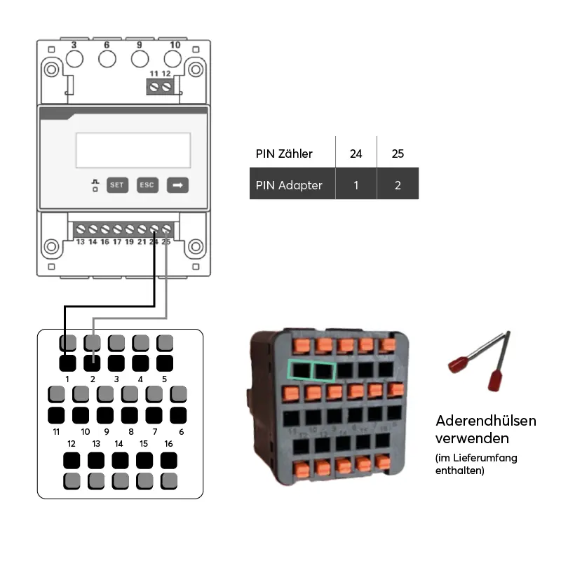
Communication DTSU and Inverter one
DTSU and Inverter vision ONE communication - pin assignment
| Pin of the meter | Port/device | Conductor cross section | Outer diameter | ||
| Outer diameter Communication | 24 | Pin 1 Counter adapter on inverter | 0.25 - 1.5 mm2 shielded, two-core twisted outdoor cable, min. Cat. 5e
| 4 mm - 11 mm
| |
25 | Pin 2 Counter adapter on inverter | ||||
5 | Pin 485A on the SOLARWATT Charger (optional) | ||||
6 | Pin 485B on the SOLARWATT Charger (optional) | ||||