- SOLARWATT Battery & Inverter vision
- Installation
- Installing Battery vision
Installing Battery vision
This page describes the installation of the Battery vision top pack and the Battery vision packs.
Table of contents
Install the battery packs
Observe all Safety Instructions and requirements for the installer.
Observe the Specifications for the installation location and the maximum and minimum installation distances for the inverter, meter and battery.
Observe the Information on the scope of delivery for the inverter, meter and battery.
Video: Assembling Battery vision
- Screw four feet (included in the Battery vision top pack box) to the first standard Battery vision pack (hereinafter referred to as pack) that will act as the bottom pack module
- Position the pack against the wall so that the LED display is on left-hand side of the pack when facing it
- Adjust the feet as required such that the pack sits level on the floor
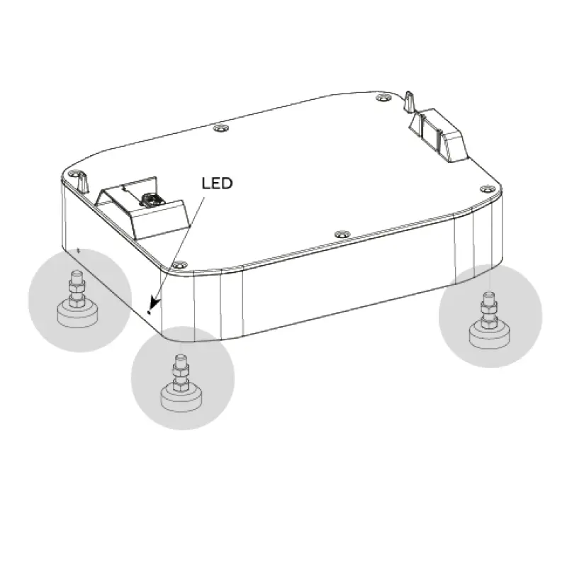
Align Battery pack (LED on left), screw on feet
- Align the battery module so that it sits straight in front of the wall using a plumb line
- Check the pack is sufficiently spaced away from the wall (approx. 38 mm) before stacking the rest of the battery tower
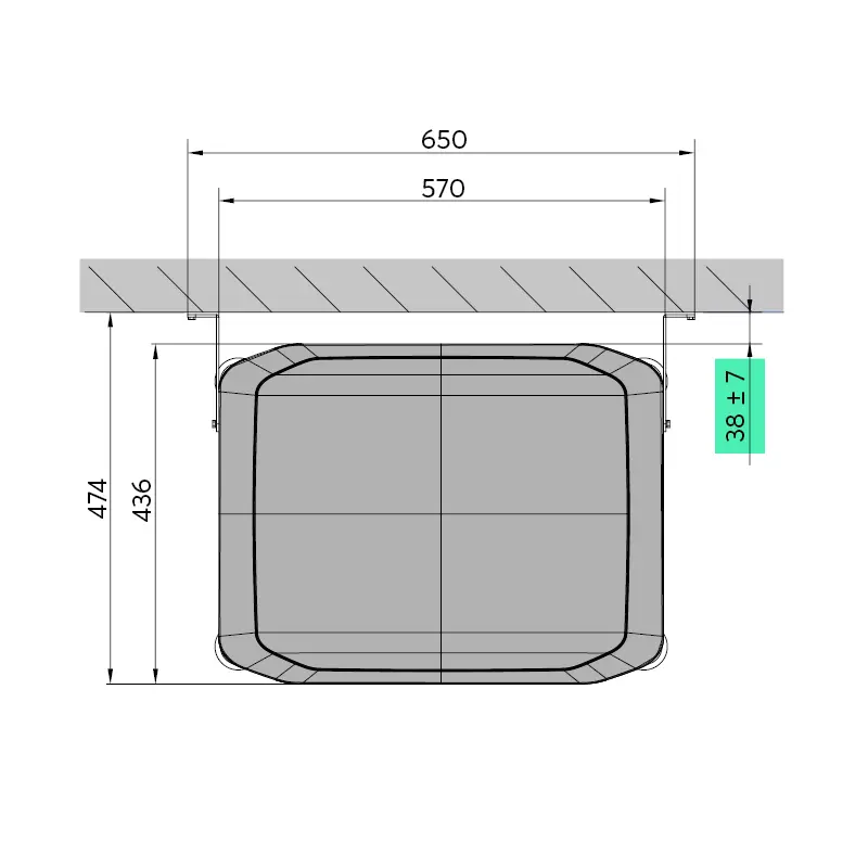
Check the wall clearance before the entire battery tower is stacked
- Insert the jumper plug (included in the Battery vision top pack box) into the connection socket at the bottom of the bottom pack and make sure it engages audibly
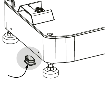
Fitting the jumper plug
- Stack the battery modules (up to 6 standard packs)
- Stack the top pack last

Stacking Battery vision packs
- Secure each battery module on both sides with the fixing screws (included in the box of each pack)
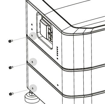
Fix each Battery pack on both sides
- Attach the wall bracket (included in the scope of delivery) to the top pack
- Make markings on the wall and drill holes for the screw fixings
- Attach the top pack to the wall on both sides using the two wall brackets
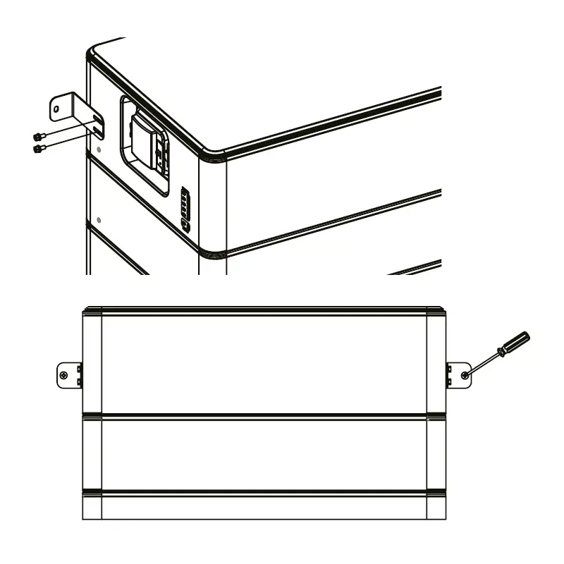
Fix the battery to the wall with 2 wall brackets
Connect the grounding cable
The Battery packs are connected to each other in the battery tower on the earth side via the connector. The top pack must be safely earthed to the house installation via earthing cables.
Grounding cables and additional cable lugs are included in the Battery vision top pack box.
- Connecting the grounding cable
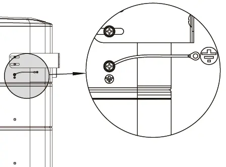
Connecting the grounding cable to the top pack
Thread cables through the cable cover
(optional)
If a cable cover was ordered:
- Thread the BMS and battery cables (coming from the inverter) through the side of the cable cover
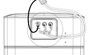
Connect the BMS cable to the battery
- Connect the BMS cable (coming from the inverter) to the BMS port on the top pack (RJ45 outdoor plug)
- Tighten the mechanical strain relief (outdoor seal at the same time)
Connect the DC battery cable to the battery
- Press the battery cable (coming from the inverter) into the holes for mechanical strain relief on the top pack
- Connect the battery cable to the BAT+ and BAT connection on the top pack battery module
Attach the cable cover
(optional)
If a cable cover was ordered:
- Close the cap and snap the cable cover into place